Motor Control Wiring Diagram Pdf
Imagine trying to wire a pushbutton station for a 100a motor using 3 awg conductors. Wiring diagram calls for something different.
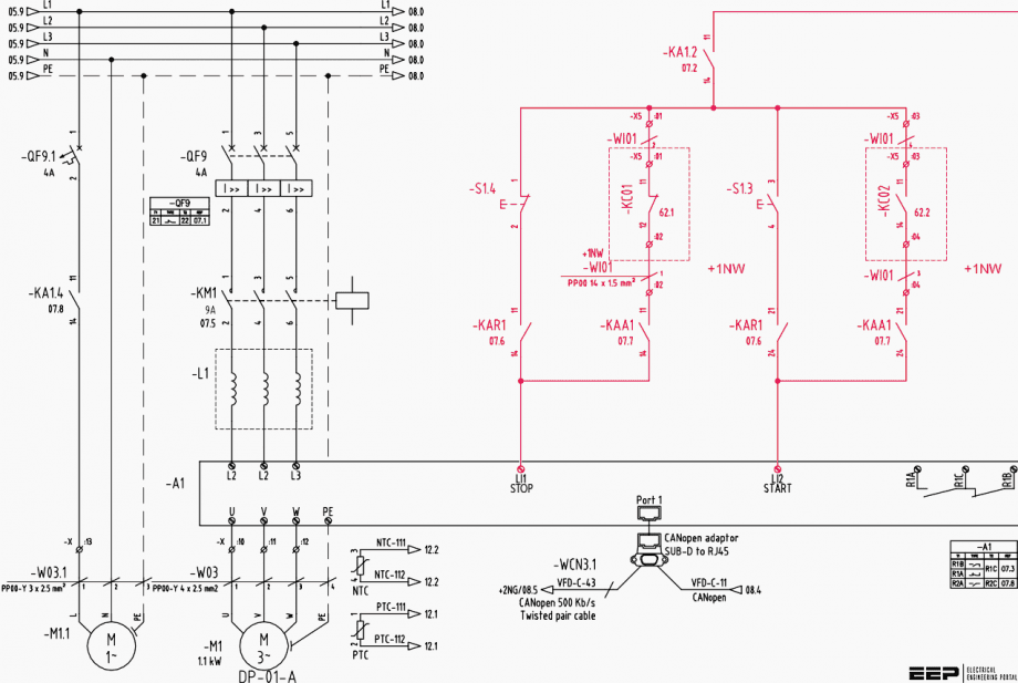
3 Phase Induction Motor Driver Vfd Motor Control Circuit Diagram Pdf kasiadorota
Wiring diagrams show the connections to the controller.

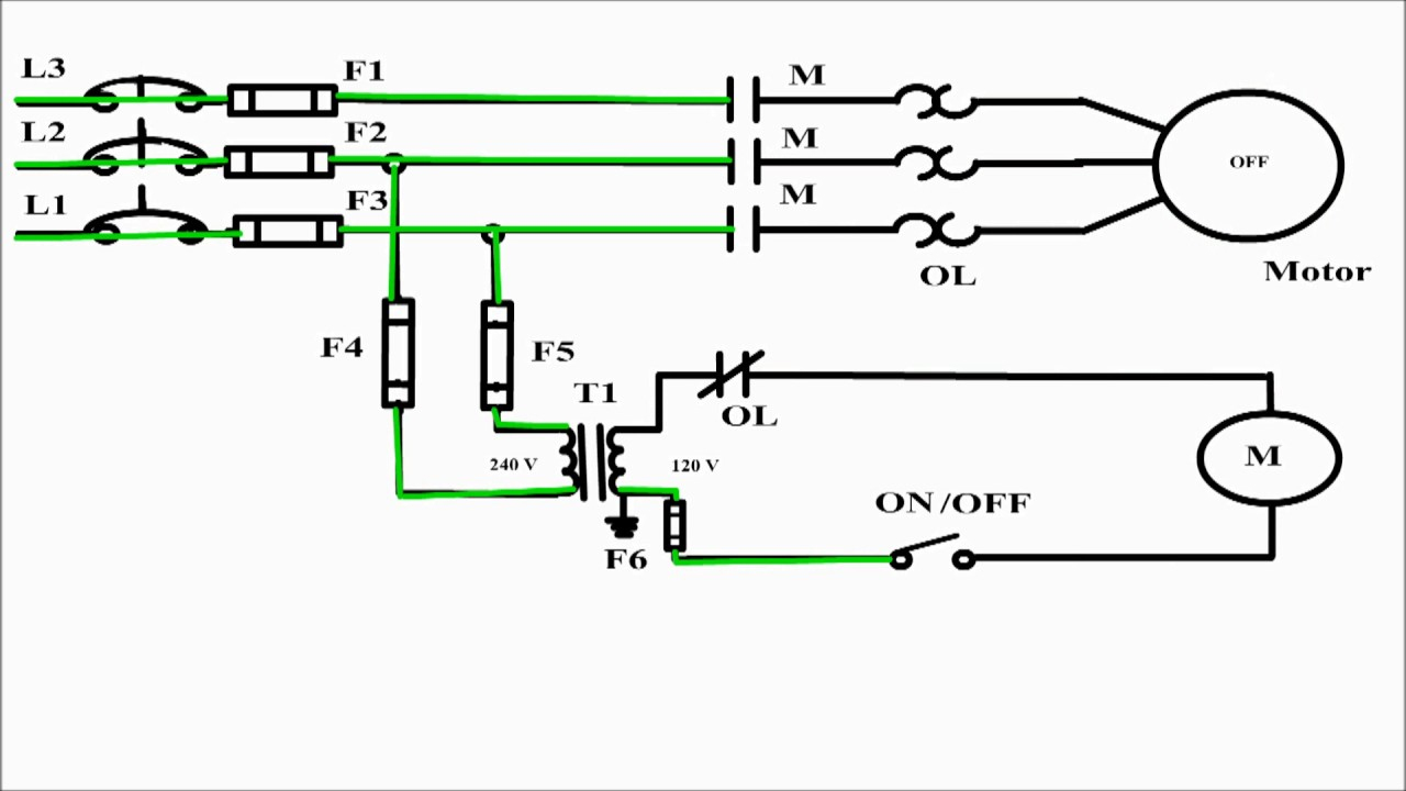
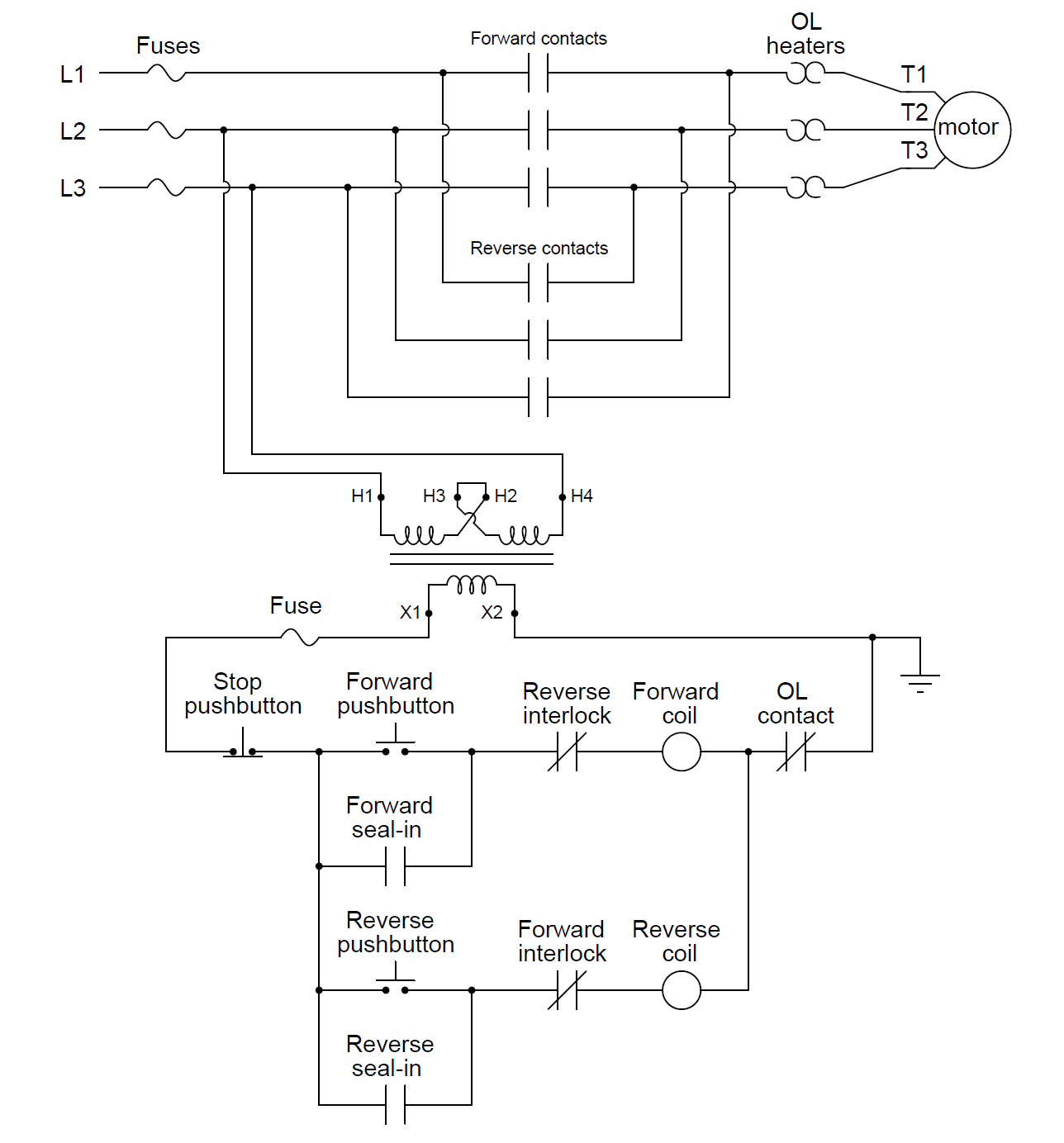
Motor control wiring diagram pdf. Many smaller motors use the same size Diagram motor control circuit diagram forward reverse 12 mb new update december 18 2020 full version hd quality forward reverse alexwiringtest locchioelaluna it simple motor control wiring diagram pdf eia 568a wiring diagram stereoa 2020 jeanjaures37 fr pin by etonia tava on electronic engineering in 2020. FIle 00836 question 4 interpret this ac motor control circuit diagram, explaining the meaning of each symbol:
The wiring diagram and physical layout motor control circuit forward basic for 88 electric ac circuits worksheet applied sequence controls starters of dol starter direct online manual star delta ladder logic အ က နည ပည electrical 1 principles steppermotor controller with attiny13 handbook machines bldc algorithms renesas. Please download these motor starter wiring diagram pdf by using the download button, or right visit selected image, then use save image menu. In the united states for low voltage motors below 600v you can expect either 230v or 460v.
The control circuit may not be at the same voltage as the power circuit. We are happy to explain further or talk about custom options if you don’t see what you’re looking for. Wiring diagrams show, as closely as possible, the actual location of each component in a circuit, including the control circuit and the power circuit.
Basics 9 4.16 kv pump schematic : Multiple function equipment such as that used for automatic emergency power switching. Basics 8 aov elementary & block diagram :
What happens when someone actuates the. Collection of motor starter wiring diagram pdf it is possible to download free of charge. The first step is to figure out the voltage of your phases.
Better understanding of motor control wiring diagrams. Contactors and motor starters including short circuit and overload protection devices. Www.eaton.com technical data basic wiring for page 4 effective:
Standard diagram symbols td03309004e for more information visit: Vfd motor control circuit diagram pdf.make sure if you have a bypass function that both the vfd and bypass mode operate the motor in the same direction. This form of electrical diagram is sometimes referred to as a “schematic” or “line” diagram.
These diagrams are current at the time of publication, check the wiring diagram supplied with the motor. Refer to the motor manufacturer’s data on the motor for wiring diagrams on standard frame ex e, ex d etc. If you are unsure, please feel free to contact us.
When the voltage of the control and power circuits is the same, it is referred to as common control. Motor 3ct to 120 v separate control * ot is a switch […] Basics 14 aov schematic (with block included) basics 15 wiring (or connection.
Inst maint & wiring_5.qxd 20/11/2015 11:37 am page 6 3 phase motor wiring diagram pdf. Basic wiring for motor control the diagram and physical layout 3 phase ac sequence controls starters 88 diagrams pdf circuits ladder logic of electric circuit following chegg basic wiring for motor control technical data guide eep the wiring diagram and physical layout of equipment inside motor control centre eep basic wiring for motor […]
It is your job to improvise a solution! These diagrams are current at the time of publication, check the wiring diagram supplied with the motor. Basics 13 valve limit switch legend :
Diagram dd6 diagram dd7 m 1 ln e diagram dd8 ln. Wiring diagrams for the various configurations are below. Control circuit devices and switching elements.
Ancillary equipment such as terminal blocks used to connect copper conductors. Wiring diagrams, sometimes called “ main ” or “ construction ” diagrams, show the actual connection points for the wires to the components and terminals of the controller. We 'hope this booklet furthers this purpose, c o n n s plate
Wiring diagrams help technicians to find out how a controls are wired to the system. The simplest schemes are shown below. Wiring diagram book a1 15 b1 b2 16 18 b3 a2 b1 b3 15 supply voltage 16 18 l m h 2 levels b2 l1 f u 1 460 v f u 2.
The control circuit is separate from the motor circuit. They show the relative location of the components. Basics 10 480 v pump schematic :
Star Delta Starter Control Wiring Diagram With Timer Pdf
Electrical Control Panel Wiring Diagram Pdf Download

Star Delta Wiring Diagram Pdf / Diagram Wiring Diagram Of Wye Delta Motor Control Full Version
3 Phase Motors Wiring Diagram Cadician's Blog
Wye delta motor control wiring diagram pdf

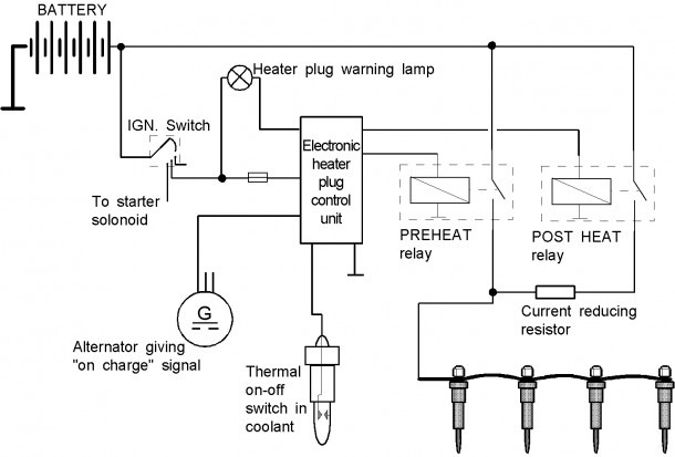
Diesel Engine Diagram Pdf
Plc Control Panel Wiring Diagram Pdf Download

Motor Control Circuit Wiring Instrumentation Tools
Three Phase Motor Control Circuit Diagram Pdf

Contactor Wiring Diagram Pdf

Wye delta motor control wiring diagram pdf

55 New 3 Phase Motor Starter Wiring Diagram Pdf

Electrical and Electronics Engineering Types of Motor Control Schematics!! Electrical circuit

Motor Control Wiring Diagrams Beccaobergefell
Leeson Electric Motor reversing on Drum switch

3 Phase Motor Starter Wiring Diagram Pdf Wiring Diagram
Dol Starter Wiring Diagram 3 Phase Pdf

Dol Starter Wiring Diagram 3 Phase Pdf

Forward Reverse Motor Control Diagram For 3 Phase Motor
